Measure Power Supply Ripple With Oscilloscope Uk
A multimeter’s DC reading can look perfect while a regulator still injects noise into audio, sensors or logic. To measure power supply ripple with an oscilloscope you need a time-domain view: AC coupling, a short ground path and enough vertical sensitivity to see millivolt-scale AC riding on the DC rail. This UK bench checklist is educational method—not a calibration certificate.
Why a DMM hides what a scope shows
Average or even True RMS meter modes summarise voltage; they do not show the shape or frequency content of ripple. Public how-to guidance emphasises AC coupling, short grounds and mV/div settings precisely because multimeters cannot display ripple properly. Use the meter to confirm the DC level, then switch to the scope for the AC component.
UK bench checklist (PSU and DC-DC)
- Power down and set up safely on an isolated low-voltage supply or powered board you are authorised to test. Do not improvise live UK mains probing.
- Confirm DC with the meter so you know the expected rail before looking at millivolts of AC.
- Select AC coupling on the scope channel so the large DC offset does not fill the screen.
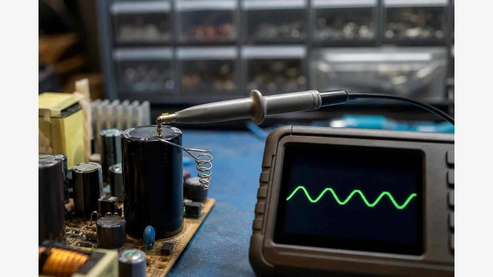
- Minimise the ground loop: spring tip or short ground spring at the output capacitor—not a long flying crocodile lead.
- Increase vertical sensitivity into the mV/div region until the ripple is visible without clipping.
- Use a bandwidth-limit habit when comparing to datasheets: industry ripple guidance often references measurements with probe-loop control and typical 20 MHz bandwidth-limit conditions.
- Note load and temperature: ripple often changes with load steps; capture both idle and loaded states.
- Cross-check with a second channel if you need to compare input versus output of a DC-DC stage.
Safety warning: Do not probe UK mains conductors unless you have appropriate category-rated instruments, differential method knowledge and training. This article covers low-voltage PSU and DC-DC observation on a repair or hobby bench.
Where handheld scopes help—and where technique matters more than MHz
A single-channel 10 MHz handheld is suitable for everyday power-supply ripple observation on repair benches. Probe technique usually dominates: a sloppy ground loop can invent “ripple” that is mostly pickup. These tools are not positioned for high-speed RF analysis, and you should not publish unsupported numerical accuracy claims from a casual capture.
Keeping a True RMS meter on the same tool
See the ZOYI ZT-702S on the product page. Ripple work on a small DC supply is mostly about how you connect, not about owning a 100 MHz bench scope. A single 10 MHz channel is enough to see the hump of a tired electrolytic on a hobby supply or a LED driver, provided you AC-couple, keep the ground lead short, and set the volts per division fine enough that the ripple stands clear of the centre line. The ZOYI ZT-702S is that kind of handheld: 10 MHz, one channel, 48 MS/s, plus a 9999-count True RMS meter for the DC level beside the trace. The screen is 2.8 inches. Compensate the probe on the fixed 3 V / 1 kHz square-wave port so a slow edge is not the probe talking. Scope input stays within 150 V peak, which covers a lot of low-voltage rails and does not cover the mains side of a supply. Measure mains with a properly rated meter method, not with the scope probe. English menus and USB-C charging suit a field visit. The spare probe set is there because ripple checks are hard on ground leads. The live page lists this meter at £98.46 including VAT. Use the scope to see whether the ripple grows with load. Use the meter to see whether the DC has already sagged. If the specification you are chasing quotes a 20 MHz bandwidth limit, say so in your notes and do not pretend a 10 MHz handheld is that measurement. For a quick yes-or-no on a 5 V or 12 V rail, it is a practical instrument. Set up the same way each time so the pictures compare. AC-couple the channel, put the probe tip on the rail, and put the ground on a local ground next to the capacitor you care about. Start at a fine volts per division and a timebase that shows the mains hump or the switching edge, whichever the supply uses. Note the load. Ripple that looks fine at idle and large at full load is the usual tired-capacitor story, and the meter should show whether the DC has sagged at the same time. Keep the scope probe off the mains input. If you need the DC number for the log, use the meter and write both figures. Compensate the probe first, or you will chase a rounded edge that is only the lead. A 10 MHz handheld is for this yes-or-no on low-voltage rails. Quote the bandwidth you used when the customer specification names a different limit. Write the bandwidth you used in the same note as the millivolts, so the next person knows this was a 10 MHz handheld and can repeat the connection. Add the load you used and whether the channel was AC-coupled.ZT-702S handheld ScopeMeter. For field kit context see portable oscilloscope for field service, and for combo economics see the 3-in-1 guide.
FAQ
Why do people mention a 20 MHz bandwidth limit?
Many ripple specifications are defined with a bandwidth limit (commonly 20 MHz) so measurements stay comparable. Match your method to the datasheet condition instead of maximising noise bandwidth blindly.
Can I measure ripple on UK mains with this method?
Not with casual single-ended probing. Mains work needs appropriate CAT practice and often differential approaches—outside the scope of this hobby/repair checklist.
Is this a substitute for calibrated lab measurement?
No. Treat captures as diagnostic insight for troubleshooting, not certified metrology.